
This article provides a comprehensive technical overview of MTE. The discussion is structured to first establish the fundamental operational concepts, including the pointer and memory tagging mechanisms. Subsequently, the focus shifts to practical implementation aspects, detailing the methods required to detect and verify MTE support and enablement across various computing platforms.
1- Executive Summary
Memory Tagging Extension (MTE) is a hardware-assisted memory safety feature introduced in the Arm8.5-A architecture and subsequent versions. Its deployment depends not only on the architecture but also on explicit enablement by chipset and platform vendors.
The primary goal of MTE is to mitigate critical memory and stack attacks (such as Buffer Overflows, Stack Smashing, and Use-After-Free vulnerabilities). This is achieved by assigning a unique 4-bit tag (Key) to both the pointer and the corresponding 16-byte memory granule. The processor checks for tag consistency on every memory access; a mismatch triggers an immediate fault, effectively preventing pointer manipulation and malicious control flow alteration.
2- Basic Concepts
2-1- MTE - Tag Pointer
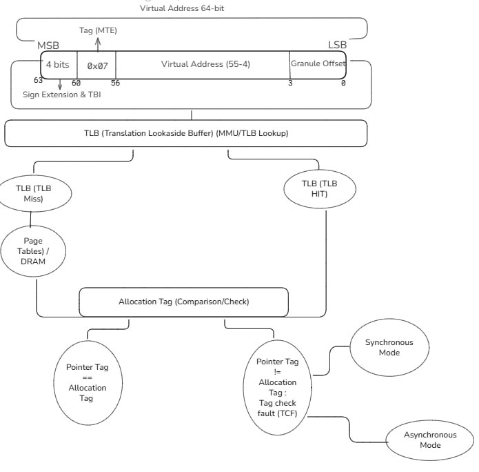
The core concept of the Memory Tagging Extension (MTE) relies on a simple yet highly effective system of assigning tags to memory regions and pointers. This is a region-based protection mechanism where the process begins by attaching a unique Pointer Tag to a virtual memory address (a pointer).
Crucially, this tag is not stored in the least significant bits; instead, MTE leverages the Top Byte Ignore (TBI) feature of the 64-bit Arm architecture. Specifically, a 4-bit tag (Key) is placed within the previously unused upper bits (56-59) of the 64-bit virtual address.
When a memory block is allocated, a random 4-bit Allocation Tag is generated. This same 4-bit value is subsequently integrated into the pointer's upper bits by the memory allocator using bitwise logical operations (such as masking and shifting) to ensure the address remains valid while carrying the tag.
When the CPU attempts to access the memory location (using Load or Store instructions), it simultaneously checks if the Pointer Tag matches the Allocation Tag of the targeted 16-byte memory granule. If the tags mismatch, the CPU raises an immediate Tag Check Fault (TCF), terminating the operation before a memory corruption vulnerability can be exploited.
MTE Architecture - Pointer and Memory Tagging
2-2- Granule & Granule Offset
The Granule is a fundamental security concept in memory management, used by ARM's MTE to divide memory within each Page. A standard Page size is 4096 bytes (4 kilobytes). Within this page, memory is divided into Granules, each with a size of 16 bytes. This means that each Page contains 256 Granules (4096 / 16 = 256).
Each byte within a Granule unit can be accessed through an offset. This Granule Offset is determined by 4 bits (Bits 3 to 0) in the LSB area of the Pointer. The primary function of the Granule is not just to enable reading bytes but to serve as the smallest security unit to which a single Allocation Tag is assigned for hardware-based memory protection.
Example: Representation of the relationship between the page and the granules and the offset.
Granule offset (4 bits) : 1001 (0x9)
Base page address : 0x10000000
Granule Offset Calculation
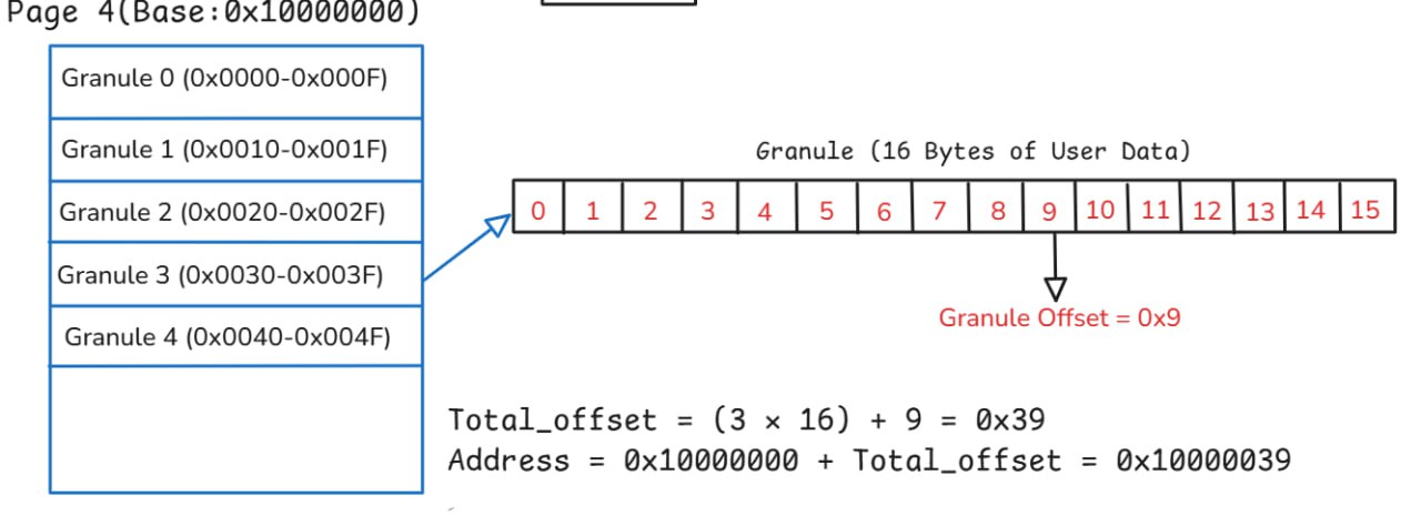
In this image, we notice Page number four with the address 0x10000000 as an example. The goal is to determine the Granule offset (4 bits): 1001 within a Granule that is 16 bytes in size. For example, let's assume the target Granule is the third one. As we can see, the Granule is divided into 16 bytes (0-15), and we can directly determine the Granule offset, which is 0x9, meaning the ninth byte within the Granule.
And also, the method for calculating the Effective address is as follows:
Effective address = PageBase + (GranuleIndex × 16) + GranuleOffset
- PageBase: It is the physical address of the beginning of a memory page (usually 4 kilobytes) after the translation (Virtual to Physical) performed by the MMU using Page Tables.
- GranuleIndex: It is the number of the required Granule unit within the page (from 0 to 255).
- GranuleOffset: It is the 4 least significant bits in the index (value 0-15).
And let's change the values to obtain the effective physical address of the data within the memory unit in the ARM MTE system:
Total_offset = (3 × 16) + 9 = 0x39

Address = 0x10000000 + Total_offset = 0x10000039
This means that the PA within the memory unit in the ARM MTE system is 0x10000039.
2-3- Tag Forgery
Tag Forgery in the context of MTE analysis is the deliberate manipulation of the Pointer Tag (the 59 - 56 bits of the address) by an analyst. This is done by injecting an incorrect tag value (0x6) that is guaranteed not to match the legitimate Allocation Tag assigned to the memory region.
The diagnostic goal of this experiment is to validate the MTE mechanism is active and functioning. If MTE protection is indeed enabled, the attempted access with the forged tag will invariably trigger a TCF, thereby proving that every memory access is strictly conditional on a successful tag check.
2-4- Mask Isolation
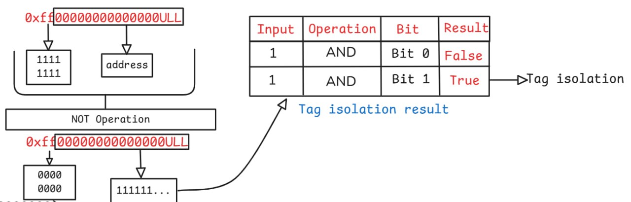
Mask isolation is a bit manipulation method used to extract a specific subset of bits from a larger address value, such as the 64-bit tagged pointer in MTE. This process is achieved by creating a custom mask and applying the bitwise AND operator.
The mask strategically defines which bits are relevant and which are not:
- One bits(1): are placed in the positions corresponding to the bits we want to isolate and retain (e.g., the MTE Pointer Tag). Applying AND with 1 ensures the original bit value remains unchanged.
- Zero bits (0): are placed in the positions corresponding to the parts we want to eliminate or clear (e.g., the Virtual Address, TBI, and Granule Offset). Applying AND with 0 forces the corresponding bits in the address to zero, thus successfully isolating the target value.
The primary goal of the zero bits is to neutralize all irrelevant parts of the address to ensure the desired bits (like the Pointer Tag) are cleanly extracted without contamination.
Tag Isolation Process
2-5- NOT & AND Operation
The NOT operation (~) is a bitwise logical operator that aims to invert the binary value of every bit in an operand. For any given bit, one (1) flips to zero (0), and vice versa. In the context of pointer tagging, this is a crucial step for mask isolation.
When NOT is applied to a mask like 0xff00..., it reverses the roles of the bits: the eight most significant bits (0xFF) flip from ones to zeros, while the remaining 56 bits flip from zeros to ones. This inversion strategically creates a final mask that allows us to clear the old tag (using the new zeros) while protecting the underlying Virtual Address (using the new ones) in the subsequent AND operation.
Take a look at this picture, it's a table that illustrates the operations of the And, OR operators.
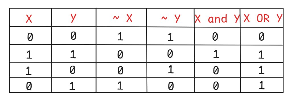
Logic Operations Table
2-6- Shifting
Left shift is a process aimed at doubling the value or moving the bits forward to increase the exponent, and the empty bits on the right are filled with zeros.
- For example, it is used to place the tag or offset in its correct position within the pointer (like tag << 56).
Right Shift:
Right shift (represented by the operator >> in C language) is a process aimed at dividing the value or shifting the bits backward to reduce the exponent value.
- It is used to extract the tag value (Tag) or the Offset from the entire address (like ptr >> 56 to extract the tag).
- For example, it is used to place the tag or offset in its correct position within the pointer (like tag << 56).
Example of bitwise shift to the left and right:
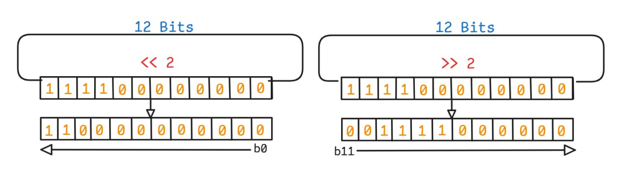
Bit Shifting Operations
3- MTE Detection
The process of detecting and verifying MTE support involves several steps:
- Allocating a page in memory using the mmap function to obtain the address of this page and manipulate it "Memory allocation"
- Manually placing a tag within this title about reversing "not opr" bits and using the And logic to implement tag isolation.
- Manipulate the Tag by changing the Tag value to a different value to activate TCF.
3-1- Allocate Memory & Get Address
Function to allocate memory and get the address:
void *allocMemory(size_t size)  //page size (4096)
{
   void *ptr = mmap(NULL, size,
                     PROT_READ | PROT_WRITE,
                     MAP_PRIVATE | MAP_ANONYMOUS, -1, 0);
    if (ptr == MAP_FAILED)    //failed create memory page
    {
        perror("[-] Failed to allocate MTE memory");
        return NULL;          //return null -> Exit prog
    }
    return ptr;   //return address
}
3-2- Set Tag & Get Tag
Macros for getting and setting tags:
#define get_tag(ptr) \  //Function to get Tag
    ({ uintptr_t ___ptr = (uintptr_t)(ptr); (int)((___ptr >> 56) & 0xff); }) //0xff -> tag

#define set_tag(ptr, tag) \  //Function to set Tag
    ({uintptr_t ___ptr = (uintptr_t)(ptr); \
       ___ptr = (___ptr & ~0xff00000000000000ULL) | (((uintptr_t)(tag) & 0xff) << 56); \
       (void *)___ptr; })
3-3- Tag Manipulation
Complete implementation for tag verification and manipulation:
int tagVerf(size_t size)
{
    printf("[+] Starting MTE Pointer Tag Verification Demo.\n");
    size_t sizeT = (size > 0) ? size : 4096; //page size
    void *basePointer = allocMemory(sizeT);
    if (basePointer == NULL)
    {
        perror("[-] Failed to allocate MTE memory (mmap failed)");
        return -1; //exit (failed alloc memory)
    }
    int intailTag = 0x5;    //default tag (0x5) -> 4 bits
    void *ptrTagged = set_tag(basePointer, intailTag);
    __arm_mte_set_tag(ptrTagged);     // set tag in address
    printf("[+] Pointer Tag: 0x%x\n", get_tag(intailTag));
    printf("[+] Memory Tag: (Assumed 0x%x after __arm_mte_set_tag)\n", intailTag);
    if (__arm_mte_check_support() == 0)  //check support MTE
    {
        printf("\t[+] INFO: MTE system support seems to be ON.\n");
    }
    else
    {
        printf("\t[!] WARNING: MTE not supported or check failed (running in non-MTE mode / stubbed functions).\n");       //not support
    }
    int forged = 0x6;         // Tag manipulation
    void *ptrForged = set_tag(basePointer, forged); //Change the tag in the address.

    printf("\n--- Tag Forgery Attempt ---\n");
    printf("[+] Forged Pointer Address: 0x%016lx  Forged tag: 0x%x\n",
           (unsigned long)(uintptr_t)ptrForged, get_tag(ptrForged));
    printf("[+] Expected Memory Tag: 0x%x\n", intailTag);
    printf("\t[+] Attempting to access memory with forged tag (0x%x vs 0x%x)...\n",
           get_tag(ptrForged), intailTag);
    errno = 0;
    char valueAccess = 0;
    volatile char *p = (volatile char *)ptrForged;
    valueAccess = *p;
    if (errno != 0)
    {
        perror("\t[!] Read fault");
    }
    else
    {
        printf("\t[+] SUCCESS (or no MTE fault): value read = 0x%02x '%c'\n", (unsigned char)valueAccess,
               (valueAccess >= 32 && valueAccess <= 126) ? valueAccess : '?');
    }
    munmap(basePointer, sizeT);   //free page address
    return 0;            //finish func
}

int main(void)
{
    return tagVerf(4096); //default page size == 4096
}
4- Conclusion
This analytical study has demonstrated that the ARM Memory Tagging Extension (MTE) represents a fundamental shift towards hardware-enforced memory security. MTE's success relies on the precise integration of several conceptually simple yet robust architectural mechanisms:
Precise Physical Addressing: The addressing mechanisms confirm that memory access is localized by accurately deriving the Physical Address PA. This process precisely integrates the Page Base Address with the Granule Index and the specific Granule Offset (0x10000039).
Rigid Tag Checking: MTE's protection is enforced by a comparison layer that demands a match between the Pointer Tag and the Allocation Tag stored in memory metadata. As validated by the diagnostic Tag Forgery experiment, any mismatch immediately triggers a Tag Check Fault TCF, stopping memory corruption attacks before they can be exploited.
In summary, MTE's strength lies not only in its ability to detect temporal errors like Use-After-Free but also in its capacity to elevate memory security from a software layer to a hardware-enforced architectural primitive. This advancement establishes a robust foundation for developing more secure software resilient against a wide range of memory corruption vulnerabilities.